The ArcGIS Event Editor allows you to add linear events to dominant routes where route concurrences exist.
Concurrent routes
Concurrent routes are routes that share the same centerlines; that is, they travel the same pavement but are modeled with different measures. This relationship may exist to model two routes with different directions of calibration, to model different directions of travel on the highway, or to model locations on highways where multiple routes converge into a common roadway for a subset of their paths. Where these concurrent routes exist, you can choose a route that's considered dominant using a set of rules.
The Event Editor app allows you to add linear events to dominant routes. For example, in the following image, there are three routes with route IDs: 100 with Name A, 200 with Name B, and 300 with Name B.
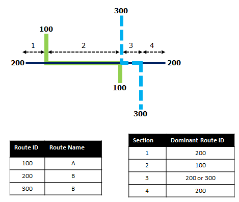
路径优先级规则设置为:路径名称越小,路径优先级越高。 使用此条件,路径 100 为最高优先级路径,并且路径 200 和 300 具有相同的优先级。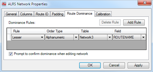
If you want to add linear events from the start of route 200 to the end of route 200, that process is done in four sections.
- Section 1—Route 200 is the dominant route, since no other route exists in this section; therefore, the event will be added to route 200.
- Section 2—Route 100 has the greater order of dominance; therefore, the event will be added to route 100.
- Section 3—Both route 200 and route 300 have the same order of dominance; therefore, the event will be added to the route of your choice.
- Section 4—Route 200 is the dominant route, since no other route exists in this section; therefore, the event will be added to route 200.
注:
- 请配置路径优先级规则以访问此功能。
- 属性集中的事件应该属于所选路径 ID 的同一网络。
- 每次可以为一条路径添加事件。
To add linear events to dominant routes, complete the following steps:
- Open ArcGIS Event Editor and, if prompted, sign in to your ArcGIS organization.
- Click the Edit tab.
- In the Edit Events group, click the Line Events button
 .
.The Add Linear Events widget appears.
注:
The selections for the network to and from method and measure can be configured in advance when configuring, creating, or editing the default settings for attribute sets.
Learn more about configuring and creating and editing default settings for attribute sets.
- Click the Network drop-down arrow and choose the network that will serve as a source linear referencing method (LRM) for defining the input measures for the new events.
The network is an LRS Network published as a layer in the Event Editor.
You can specify the LRS Network to be used as the linear referencing method (LRM) for defining the start and end measures of the new linear event.
- Provide the route ID on which the event's From Measure will be located.
提示:
You can also click the Select a Route on the Map button
 to select the route on the map.
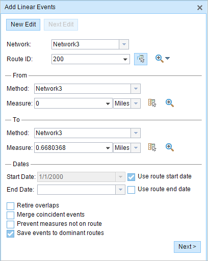
- In the From section, choose the first option (with the suffix Network) in the Method drop-down list.
- Provide the intended start location for the new linear event along the route using any of the following options:
- Provide the value in the Measure text box.
- Click the Select From Measure on the Map button
 and choose the From Measure value along the route on the map.
 - Click the Measure drop-down arrow and choose either Use the Route Start or Use the Route End as the From Measure value for the event.
If you provide the From Measure value, you can choose the unit of measurement for that value using the drop-down arrow. The From Measure value will be converted into LRS units before saving the newly added events. For example, if the LRS is in miles and you've specified 528 feet as the From Measure value, the newly added events will have a From Measure value of 0.1 miles, because 528 feet equals 0.1 miles.
A green plus symbol appears at the selected location on the map.
- For the To Measure value, repeat steps 4 through 6 for the To section.
A red x symbol appears at the selected location on the map.
- Choose the date that will define the start date of the events by doing one of the following:
- Type the start date in the Start Date text box.
- Click the Start Date drop-down arrow and choose the start date.
- Check the Use route start date check box.
The start date defaults to today's date, but you can choose a different date using the date picker.
注:
If you configured your Event Editor instance to not allow dates before the start date of the route, and you provide a date before the start date of the selected route in Start Date, a warning message appears alerting you to choose a date on or after the start date of the selected route.
- Choose the date that will define the end date of the events by doing one of the following:
- Type the end date in the End Date text box.
- Click the End Date drop-down arrow and choose the end date.
- Check the Use route end date check box.
The end date is optional, and if it is not provided, the event remains valid now and into the future.
- Choose from the following data validation options to prevent erroneous input while characterizing a route with linear events:
- Retire overlaps—The system adjusts the measure and start and end dates of existing events in such a way that the new event does not cause
an overlap with respect to time and measure values.
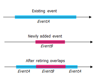
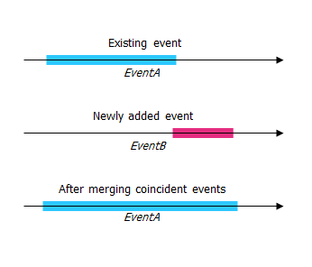
- Merge coincident events—When all attribute values for a new event are exactly the same as an existing event, and if the new event is adjacent to or overlapping the existing event in terms of measure values, the new event is merged into the existing event and the measure range is expanded accordingly.
- Prevent measures not on route—This data validation option ensures that the input measure values for from measure and to measure values fall in the minimum and maximum range of measure values on the selected route.
- Save events to dominant routes—Events are added to the dominant route in a section with concurrent routes. If enabled, any concurrent sections on the route selected allow you to choose which route the events will be added to on each concurrent section. This option is available when the network selected has dominance rules configured.
- Retire overlaps—The system adjusts the measure and start and end dates of existing events in such a way that the new event does not cause
an overlap with respect to time and measure values.
- Check the Save events to dominant routes check box.
This dominant routes option can be configured to be checked or not checked by default using the Event Editor configuration file.
- Click Next.
The route dominance table appears.
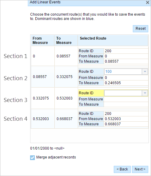
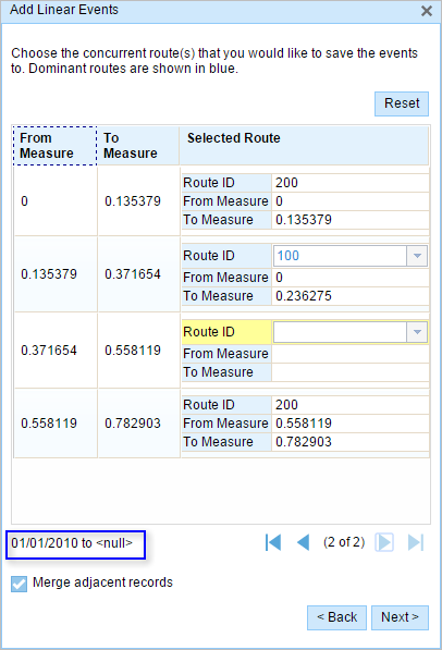
The From Measure and To Measure columns show the values for each section of the chosen route from the previous pane. The From Measure and To Measure boxes under Route ID show the value for each dominant route where the events will be added.
A black route ID without a drop-down arrow signifies that there was a single route in that section. A blue route ID with a drop-down arrow signifies that there are concurrent routes in that section, and the blue route is selected by the software based on the route dominance rules. You can select any other route using the drop-down arrow.
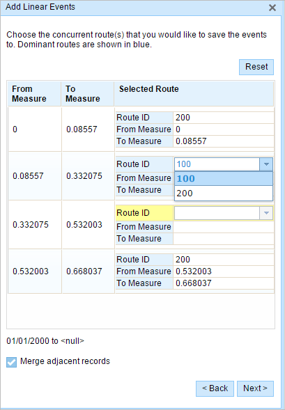
A yellow route ID box with a drop-down arrow signifies that there is an ambiguous situation in selecting the dominant route, as there is a tie in the route names of route 200 and route 300. In this case, you need to manually select a route ID using the drop-down arrow. The yellow color disappears once you've manually selected a route.
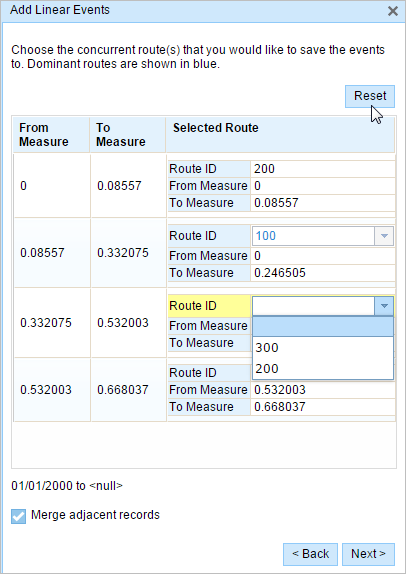
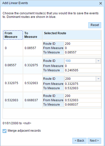
Select route 200. If you check the Merge adjacent records check box, the records in sections 3 and 4 will be merged since they have the same route ID.
- Click Next.
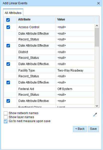
The tab showing the attribute set for the events opens. The event fields are shown under attribute group G1.
注:
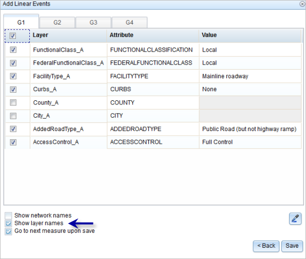
You can check the check boxes to add data for specific events within the attribute set. No records are added for the events that are not checked. As shown in the following image, no records are added to the County_A and City_A events.
- Provide the attribute information for the new event in the tables defined by attribute sets.
You can use the Copy Attribute Values tool
 to copy event attributes from another route. Click the tool and click a route on the map to copy the event attributes.
Event Editor uses a default attribute set, as seen on the Edit tab. You can modify the attribute set to create custom attribute sets or use the administrator-configured attribute set.
- Use the following options to access more information on the attribute set:
- Check the Show network name check box to show the LRS Network associated with the selected event layer.
- The list of attributes in the tables defined by attribute sets can be from more than one event layer. If you want to identify the source event layer for each attribute, check the Show layer names check box.
- Check the Go to the next measure upon save check box to prepopulate the From Measure value using the To Measure value of the present section to continue the event creation process.
- Click Save.
The new linear events are created and appear on the map. A confirmation message appears at the lower right once the newly added line events are saved.
After an event has been successfully created, you have the following two options to continue characterizing the route:
- Click New Edit to clear all the input entries in the widget and restore the default values from the geodatabase to the attribute table.
- Click Next Edit to retain all the existing entries in the widget and the attribute table for the convenience of quick editing of similar characteristics.
Concurrent routes with different time ranges
The following image shows concurrent routes with different time ranges: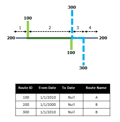
Route 200 has the From Date value of 1/1/2000, whereas route 100 and route 300 have the From Date value of 1/1/2010. Therefore, if the selected start date of the event is 1/1/2000, there are two route time ranges:
- 1/1/2000 to 1/1/2010, when only route 200 existed.
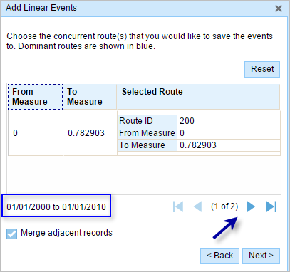
- 1/1/2010 to Null, when all three routes existed.
