Plan Routes determines how a fleet of vehicles can visit a set of stops in the least amount of time.
You provide the tool with the stops that need to be visited and the number of vehicles available to visit the stops. The tool assigns the stops to vehicles and returns routes showing how each vehicle can reach their assigned stops. Both the stop assignment and the routes along the roads are calculated in a way that minimizes overall travel time.
When stops cannot be reached, they are returned in an unassigned stops layer, which includes a field that explains the reason why the stop couldn't be assigned.
Note:
If you do not see the Plan Routes tool in the map viewer, contact your portal administrator. Your portal might not be configured for routing or you may not have privileges to run the tool.
Plan Routes versus single-vehicle routing
Most people are familiar with single-vehicle navigation, which takes a set of stops and finds the quickest route for one vehicle to visit them. Some single-vehicle navigation tools can optimally rearrange the stop order to prevent the route from backtracking on and crisscrossing itself, which ultimately minimizes the overall travel time or distance.
Plan Routes is similar, but instead of routing a single vehicle at a time, it routes many vehicles at once. Furthermore, it determines how the stops should be divvied up among the various routes and the best order in which the routes should visit the stops.
Benefits of using Plan Routes
Plan Routes offers the following benefits:
- It simplifies the otherwise difficult job of plotting routes for a fleet of vehicles.
- It generates efficient routes, which saves time and resources for the entire organization and limits fuel usage and vehicle pollution.
- It stores the results in your portal, which makes sharing routes with drivers easier.
Example: Building inspectors
A team of four building inspectors has a list of 30 jobsites they need to visit. Their manager uses Plan Routes to figure out how she can assign jobsites to inspectors so the most inspections can be performed within 8 hours—the duration of the workday.
Create a layer for start locations
The inspectors start their workday when they depart from home in their car. They drive directly to various jobsites to perform inspections and finish the day at the central office to file paperwork.
The first time the manager sets up her data to perform Plan Routes, she creates a spreadsheet listing the inspectors' names and their home addresses. She saves the spreadsheet as a comma-separated values (CSV) file named Inspectors. She signs in to the portal. Her account is in the Publisher role and, therefore, has all the necessary privileges (that is, create, update, and delete; publish hosted features; spatial analysis; and network analysis privileges). She opens the map viewer and drags and drops the Inspectors file into the map to geocode the list of addresses, which becomes a layer of points.
Knowing she will repeatedly reuse the Inspectors layer as starting locations, she saves the geocoded layer of addresses to My Content by clicking the arrow to the right of the layer and choosing Save Layer.
Create a layer for end locations
She uses a different method to add the central office to the map; she clicks Add > Add Map Notes and manually places a pin on the map where the office is located. She saves this layer as Central Office, since it will be used every workday in Plan Routes, just like the start locations.
She also saved the starting and ending location layers in a map since the map will serve as a good place to start each day generating route plans.
Add stops
The jobsite addresses to be visited are added to a spreadsheet each day, so the manager follows the same process of opening the spreadsheet of addresses, saving it as a CSV file, and geocoding the addresses by dropping the file in the map viewer.
She doesn't save the resultant Jobsites layer since she will only use it once in Plan Routes.
Run Plan Routes
In the table of contents, she clicks the arrow to the right of the Jobsites layer and chooses Perform Analysis. From there, she clicks Use Proximity > Plan Routes and begins filling out the form.
- The Inspectors layer is chosen as the starting locations of routes. (If an inspector takes a day off, she applies a filter on the Inspectors layer before opening Plan Routes to temporarily remove the inspector from the layer and subsequently from the analysis.)
- The Name field in the Inspectors layer lists the names of the workers, so she chooses Name for the Route ID field option that appears.
- The workers start their day at 9:00 a.m., so she chooses the calendar date and sets the start time to 9:00 a.m.
- She unchecks Return to start and chooses the Central Office layer as the end location.
- She makes sure that Maximum number of vehicles to route is set to four, since all four building inspectors are planning to work.
- The number of jobsites the inspectors need to visit changes from day to day. Some days, there are more jobsites than the team can visit. On those days, she can set the Maximum number of stops per vehicle parameter to the maximum number of jobsites that a worker could feasibly inspect. On other days, when the total number of jobsites is less, she uses a different method. She looks at the note that appears in the Plan Routes tool under Maximum number of stops per vehicle that tells her how many stops are in the Jobsites layer. She sees there are 30 stops in the layer and divides that number by the number of vehicles she's routing—four—to get a sense of how she could assign an equal number of stops, or jobsites, to each worker. The result is 7.5, which she rounds up to 8 to avoid leaving any jobsite out of the solution. However, she understands that some jobsites are clustered together and others are spread far apart from one another and, therefore, the time it takes to reach different sites varies. She increases this number to 12 so routes that travel shorter distances to a cluster of nearby jobsites can visit more sites. The routes that travel farther distances to outlying sites can visit fewer sites. Later, she may decide to solve the problem again using a different value for the maximum number of vehicles to compare results.
- Inspections take an average of 30 minutes, which is the value she enters in Time spent at each stop.
- She wants to limit the inspectors' workday to 8 hours, so she checks Limit the total route time per vehicle. This limit accounts for total travel time and time spent at each jobsite. If she sets the limit to 8 hours, however, the workers won't have time left after arriving at the central office at the end of their routes to file paperwork. It takes about 45 minutes for them to complete tasks at the office, so she reduces the time limit to 7 hours and 15 minutes.
- She names the output layer Routes to Jobsites and appends the date to make a unique layer name.
- She clicks Run Analysis. The tool processes and returns the results.
Communicate routes to workers
Plan Routes outputs information on how to optimally visit many stops with many vehicles; that is, it outputs a master plan in which each vehicle is assigned an individual plan detailing the stops to visit, the order in which to visit the stops, and the path to take to reach them. To execute the master plan, each driver needs to receive focused information on how to execute their part of the overall plan.
Filter by route name
The manager applies a filter on the output routes and assigned stops layers to strip out all information of the plan that is irrelevant to a particular inspector. She does this by clicking the arrow to the right of the output routes layer, choosing Filter, and setting the filter expression to start with Route Name is and end with the name of the inspector as it appears in the table of the output layer. She applies the same filter to the assigned stops layer. The map shows the route and stops assigned to one inspector.
Create maps and directions
After applying the filter, she can choose from a couple options to suit the needs of the inspector.
- She can save the map and share the link to it with the inspector, who can open the map in their mobile device's web browser.
- She can generate directions for drivers who prefer printed directions by choosing Route to all features off of the filtered stops layer. This option is available only when 20 or fewer stops are assigned to the inspector.
She creates a filter for the next inspector and repeats the process of getting directions or saving a map until all inspectors have the instructions they need.
Open assigned stops in a spreadsheet
When she is working with several inspectors who know the area well and just need a list of stops rather than directions or a map, she downloads the assigned stops layer as a comma-separated values (CSV) file and opens it as a spreadsheet. She can perform filtering, sorting, printing, and other tasks from her spreadsheet software.
To download the CSV file, she clicks the arrow to the right of the assigned stops layer and chooses Show Item Details to open the item description of the layer; she clicks Export > Export to CSV file to create a new item for a CSV file representation of the data; in the item description of the CSV file, which opens automatically, she clicks Open > Download to save the file locally.
Excess jobsites
She copies information about any jobsites that went unassigned or that couldn't be reached due to unforeseen delays and pastes it into the list of stops to use in the next day's run of Plan Routes.
Starting and ending locations
The starting and ending locations of routes, or vehicles, are as important as the locations of the stops they will visit. By knowing all these locations, the tool can assign the stops to the nearest vehicles to reduce overall travel times. In some cases, the Plan Routes tool names the output routes based on where they begin and end.
This section describes how you can specify route start and end points and how you can associate them with specific drivers, or routes. You can glance over the graphics in the following subsections and read through the one with the illustrations that best portray the start and end locations of the vehicles you are routing.
Several parameters can be used in combination to set the start and end points. To briefly introduce them, they are shown below with a short description of how they are relevant. These parameters are referenced in more detail in the subsections that follow.
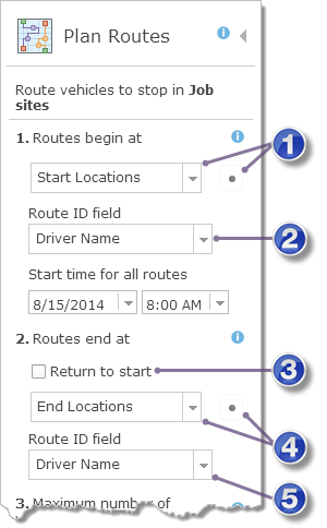
| Start layer—This parameter is always required, but what is important to know when setting values for the other parameters listed here is whether you provide one or many starting points. You can define a layer with one or more points, or you can define exactly one point using the interactive editing tool. |
| Start layer ID field—This parameter appears and is relevant only when more than one starting location is specified. It can be a route number, the driver's name, or some other unique name. |
| Return to start—Check Return to start if you want routes to end where they began; uncheck it if the routes end elsewhere. (You also need to provide one or more ending locations if Return to start is unchecked.) |
| End layer—This parameter is enabled and required when Return to start is unchecked. You can define a layer with one or more points, or you can define exactly one point using the interactive editing tool. |
| End layer ID field—Required when Return to start is unchecked and a layer with more than one point is specified as the ending location. The ID field can be a route number, the driver's name, or some other unique name. |
One starting point and returning to start
The most common problem to set up is one where all routes start and end at the same location. A charitable organization seeking to efficiently deliver donations to people in need parks its delivery vans at a single warehouse. On delivery days, volunteers load the vans, which then fan out to various stops to deliver the packages. The vans return to the warehouse after they complete their deliveries.
The start and end locations are set up in the following way:
- Start layer—The starting layer should have one point only, which can be specified interactively on the map or by choosing a layer with one point.
- Return to start—Checked.
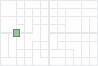
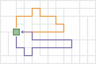
The output routes start and end at the same, single location.
One starting point and one ending point
Sometimes all routes start at one location and end at another. For instance, when planning routes for several passenger vans that will leave a depot, pick up spectators from their homes, and take them to an event, such as a concert, the depot is specified as the single starting location, and the venue of the event becomes the single ending location.
The start and end locations are set up in the following way:
- Start layer—The starting layer should have one point only (for example, the depot where the vans are parked), which can be specified interactively on the map or by choosing a layer with one point.
- Return to start—Unchecked.
- End layer—The ending layer should have one point only (for example, the event where the passengers are dropped off), which can be specified interactively on the map or by choosing a layer with one point.
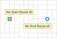
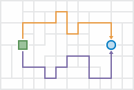
The output routes start at one location and end at another.
Because all drivers start and end at the same two locations, it is assumed any driver can drive any route, so the output routes are given names such as Route 1 and Route 2.
Many starting points and returning to start
For this problem type, each route starts from a unique point, visits its assigned stops, and finishes at the place where it began. For example, inspectors may start the day at their homes, go to various inspection sites, and return home at the end of the day.
The start and end locations are set up in the following way:
- Start layer—Include multiple points in this layer: one for each starting location (for example, a point represents an inspector's home). Note that each route is always assigned its own starting point for this problem type. If a subset of routes start at the same location, add their starting points next to or on top of each other to ensure each route has its own corresponding starting location.
- Start layer ID field—Choose the ID field for this parameter. The start layer must have a field that uniquely identifies the routes or drivers. It can be a route number, the driver's name, or some other unique name.
- Return to start—Checked.
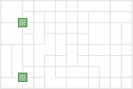
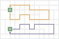
The output routes start at multiple locations and end at their starting locations.
Since the routes and their drivers start at unique locations, the ID field of the start layer must be specified. The output route names are automatically generated to be the same as the values in the ID field so the routes can be assigned and delivered to the appropriate drivers.
Many starting points and one ending point
Each route starts from a unique point, visits its assigned stops, and converges with the other routes at a single ending location for this problem type. For instance, school bus drivers in a rural school district park their buses at their homes at night. In the morning, they start their routes from home, pick up students, and drop them off at one school.
The start and end locations are set up in the following way:
- Start layer—Include multiple points in this layer: one for each starting location (for example, one point on the home of each bus driver). Note that each route is always assigned its own starting point for this problem type. If a subset of routes start at the same location, add their starting points next to or on top of each other to ensure each route has its own corresponding starting location.
- Start layer ID field—Choose the ID field for this parameter. The start layer must have a field that uniquely identifies the routes or drivers. It can be a route number, the driver's name, or some other unique name.
- Return to start—Unchecked.
- End layer—Include one point representing the ending location (for example, the school).
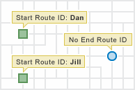
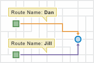
The output routes start at multiple locations and end at one location.
Since the routes and their drivers start at unique locations, the start layer has many points, and the start layer ID field property is visible and must be specified. The output route names are automatically generated to be the same as the values of the ID field so the routes can be assigned and delivered to the appropriate drivers.
One starting point to many ending points
In the one-to-many problem type, all routes start from one point, visit their assigned stops, and end at unique locations. For a utility company that needs to hang shutoff warning tags on the doors of delinquent customers, employees are offered extra pay to hang the tags on their way home from work. The employees who accept the task pick up the tags from the central office, drive to various stops to hang the tags, and end their routes at their own homes.
The start and end locations are set up in the following way:
- Start layer—The starting layer should have one point only (for example, the central office), which can be specified interactively on the map or by choosing a layer with one point.
- Return to start—Unchecked.
- End layer—Include multiple points in this layer: one for each ending location (for example, the employees' homes). Note that each route is always assigned its own ending point for this problem type. If a subset of routes end at the same location, add their ending points next to or on top of each other to ensure each route has its own corresponding ending location.
- End layer ID field—Choose the ID field for this parameter. The end layer must have a field that uniquely identifies the routes or drivers. It can be a route number, the driver's name, or some other unique name.
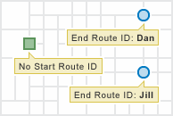
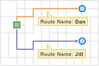
The output routes start at one location and end at multiple locations.
Since the routes and their drivers end at unique locations, the end layer has many points and the end layer ID field property is visible and must be specified. The output route names are automatically generated to be the same as the route ID values so the routes can be assigned and delivered to the appropriate drivers.
Many starting points to many ending points
In some planning scenarios, each route has unique starting and ending locations.
The start and end locations are set up in the following way:
- Start layer—Include multiple points in this layer: one for each starting location. Note that each route is always assigned its own starting point for this problem type. If a subset of routes start at the same location, add their starting points next to or on top of each other to ensure each route has its own corresponding starting location.
- Start layer ID field—Choose the ID field for this parameter. The start layer must have a field that uniquely identifies the routes or drivers. It can be a route number, the driver's name, or some other unique name.
- Return to start—Unchecked.
- End layer—Include multiple points in this layer: one for each ending location. Note that each route is always assigned its own ending point for this problem type. If a subset of routes end at the same location, add their ending points next to or on top of each other to ensure each route has its own corresponding ending location.
- End layer ID field—Choose the ID field for this parameter. The end layer must have a field that uniquely identifies the routes or drivers. It can be a route number, the driver's name, or some other unique name.
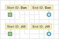
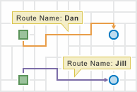
The output routes start at multiple locations and end at multiple locations.


