All geodatasets in ArcGIS contain a spatial reference. A spatial reference consists of a coordinate system, tolerance, resolution, and x,y and z domains. The coordinate system defines the datum (the shape of the earth), the map units, such as meters, feet, or longitude and latitude, and the map projection of the data. Coordinate systems can be unprojected (geographic coordinate system) or projected (state plane or UTM, for example).
Note:
All ArcGIS Server clients have the ability to request output data in any coordinate system. The server handles all coordinate conversions for you and sends data back to the client in the coordinate system it requests. You do not have to modify your models or scripts in any way.
Web applications and the Web Mercator coordinate system
Web Mercator is one of the most popular coordinate systems used in web applications because it fits the entire globe into a square area that can be covered by 256 by 256 pixel tiles. This means that the features or rasters input to your task by clients are likely to be in the Web Mercator coordinate system. Understanding the limitations of Web Mercator and how to guard against processing data in Web Mercator is essential to providing geoprocessing services in order to produce accurate results.
The link below is to a small web application that demonstrates, somewhat dramatically, how Web Mercator affects distance and area computations.
http://links.esri.com/web_mercator_measurements
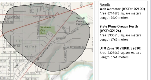
The illustration below shows measuring the area of a small polygon using the sample web application. In the right panel, three different coordinate systems are used to compute the area and perimeter length of the polygon. The State Plane Oregon North is the most accurate measurement, followed by the UTM Zone 10 measurement, and they differ by a small percentage. But notice the Web Mercator measurements; the Length measure is 9600 meters, almost half again as much as the State Plane Oregon North value of 6763. As you can see, Web Mercator is a very poor choice for computing distances and areas. Other coordinate systems, especially conformal projections over large (continental) areas, are just as poor at measuring distances and areas. (You can read a bit more about Web Mercator in this blog article: Measuring distances and areas when your map uses the Mercator projection.)

By default, most geoprocessing tools, and tasks created from them, compute distance and area using the coordinate system of the input data. Consider the effect of a client sending features to your task in the Web Mercator coordinate system; if you do nothing, the geoprocessing tools used by your task will compute distances and areas in Web Mercator (the coordinate system of the input features) and, drawing from the example above, your task may report a result of 9600 meters instead of the more accurate 6763 meters.
The remainder of this topic discusses techniques you can use to perform computations in other coordinate systems.
Using the output coordinate system environment setting
Geoprocessing environments are additional parameters that affect a tool's results. They differ from normal tool parameters in that they don't appear on a tool's dialog box (with certain exceptions). Rather, they are values you set once using a separate dialog box and are interrogated and used by tools when they are run.
The output coordinate system environment is used to instruct a geoprocessing tool to perform all computations using the coordinate system specified in the environment rather than the coordinate system of the input data. Not all tools use the output coordinate system environment. To determine if a tool uses this environment, consult the tool's reference page. At the bottom of the reference page is a list of environments that the tool uses. If the output coordinate system is listed as an environment, then the tool will use it in computations.
The output coordinate system environment is set and managed like any other geoprocessing environment; it can be set at any level and will be used by your task.
Learn more about environment settings and their use in geoprocessing services
Working with tools that do not honor the output coordinate system environment
There are many tools that do not honor the output coordinate system environment. For the vast majority of cases, the tool doesn't use geometry (such as Add Field), so the coordinate system doesn't apply. But there are some tools where the coordinate system is important, yet the tool does not honor the coordinate system environment settings. For these tools, the coordinate system of the input data is most likely used, so you have to project the input to another coordinate system if the input coordinate system is inappropriate.
For example, the Near and Generate Near Table tools both compute distances from the input features to other features (the near features). Neither of these tools honor the coordinate system environment. Rather, they both use the coordinate system of the input features to calculate distance. To use a different coordinate system, you need to project the input to the desired system.
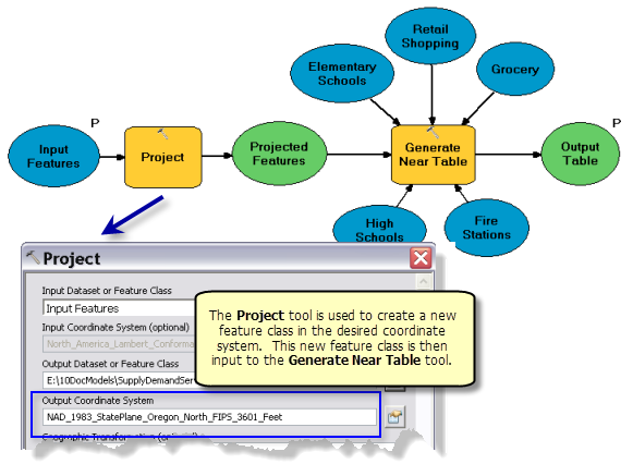
There is an example of using Generate Near Table in a A quick tour of authoring geoprocessing services. In this example, the near features are a list of five layers. For demonstration purposes, these five layers are in the Oregon State Plane North coordinate system. The model below shows using the Project tool to project the Input Features into the Oregon State Plane North coordinate system. The projected features are written to the Projected Features variable which is then input to the Generate Near Table tool. When Generate Near Table computes distances, it will use the Oregon State Plane North coordinate system since this is the coordinate system of the input features.

Tip:
The Project tool does not allow you to write the output to the in_memory workspace. Writing outputs to in_memory is a performance enhancement technique as described in Performance tips for geoprocessing services. If you need to project features but want to write to the in_memory workspace, you can use the Copy Features tool instead. Copy Features honors the output coordinate system environment, allowing you to project features in one coordinate system to another coordinate system.
Geodesic Buffer
The Buffer tool is often used in geoprocessing workflows. It is a tool that is particularly sensitive to the coordinate system. Buffer operates in two modes depending on whether the coordinate system is projected (defined by a flat, two-dimensional surface) or geographic (defined by a three-dimensional spherical surface).
When the coordinate system is geographic, geodesic buffers are created. Geodesic buffers are highly accurate as they are computed using spherical trigonometry. A geodesic buffer around a point feature will appear as an oval when projected onto a flat map, which is sometimes questioned by casual users, but these oval buffers are most assuredly correct. The opposite is also true—a point buffer that is a perfect circle (especially for buffers over a large area) is most assuredly incorrect. Geodesic buffering comes with a trade-off; they are computationally expensive to produce compared to a buffer computed on a projected coordinate system (where simple Euclidean geometry is used instead of spherical trigonometry).