The ArcGIS Event Editor allows you to add linear events to dominant routes where route concurrences exist.
Concurrent routes
Concurrent routes are routes that share the same centerlines; that is, they travel the same pavement but are modeled with different measures. This relationship may exist to model two routes with different directions of calibration, to model different directions of travel on the highway, or to model locations on highways where multiple routes converge into a common roadway for a subset of their paths. Where these concurrent routes exist, you can choose a route that's considered dominant using a set of rules.
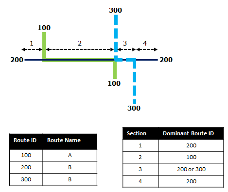
The Event Editor app allows you to add linear events to dominant routes. For example, in the following image, there are three routes with route IDs: 100 with Name A, 200 with Name B, and 300 with Name B.
Die Routendominanzregel wird so festlegt, dass die Dominanz der Route steigt, je kleiner der als Routenname verwendete Wert ist. Bei Verwendung dieser Bedingung ist Route 100 die dominanteste Route, und die Routen 200 und 300 weisen dieselbe Dominanzordnung auf. 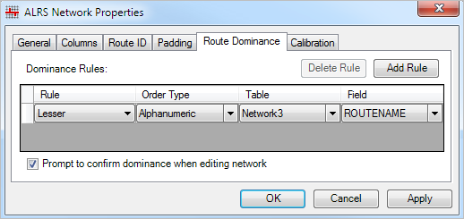
If you want to add linear events from the start of route 200 to the end of route 200, that process is done in four sections.
- Section 1—Route 200 is the dominant route, since no other route exists in this section; therefore, the event will be added to route 200.
- Section 2—Route 100 has the greater order of dominance; therefore, the event will be added to route 100.
- Section 3—Both route 200 and route 300 have the same order of dominance; therefore, the event will be added to the route of your choice.
- Section 4—Route 200 is the dominant route, since no other route exists in this section; therefore, the event will be added to route 200.
Hinweis:
- Für den Zugriff auf diese Funktionalität müssen Routendominanzregeln konfiguriert werden.
- Objekte im Attribute-Set müssen demselben Netzwerk angehören, für das die Routen-ID ausgewählt wird.
- Sie können Objekte jeweils einer Route hinzufügen.
To add linear events to dominant routes, complete the following steps:
- Öffnen Sie ArcGIS Event Editor, und melden Sie sich bei Ihrer ArcGIS-Organisation an, wenn Sie dazu aufgefordert werden.
- Klicken Sie auf die Registerkarte Bearbeiten.
- Klicken Sie in der Gruppe Objekte bearbeiten auf die Schaltfläche Linienobjekte
 .
.Das Widget "Lineare Objekte hinzufügen" wird angezeigt.
Hinweis:
Die Auswahlmöglichkeiten für die Bis- und Von-Methode und den Bis- und Von-Messwert des Netzwerks können vorab beim Konfigurieren, Erstellen oder Bearbeiten der Standardeinstellungen für Attribut-Sets konfiguriert werden.
Weitere Informationen zum Konfigurieren und Erstellen und Bearbeiten der Standardeinstellungen für Attribut-Sets
- Klicken Sie auf den Dropdown-Pfeil Netzwerk, und wählen Sie das Netzwerk aus, das als Quell-LRM zum Definieren der Eingabemesswerte für die neuen Objekte dienen soll.
Das Netzwerk ist ein LRS-Netzwerk, das als Layer in Event Editor veröffentlicht wurde.
Sie können angeben, welches LRS-Netzwerk als lineare Referenzierungsmethode (LRM) zum Definieren des Start- und Endmesswertes des neuen linearen Objekts verwendet werden soll.
- Type the route ID on which the event's From measure will be located.
Tipp:
Sie können auch auf die Schaltfläche Eine Route auf der Karte auswählen
 klicken, um die Route auf der Karte auszuwählen.
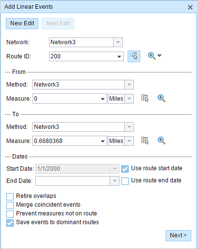
- In the From section, choose the first option (with the suffix Network) in the Method drop-down list.
- Provide the intended start location for the new linear event along the route using any of the following options:
- Type the value in the Measure text box.
- Click the Select From Measure on the Map button
 and choose the From measure value along the route on the map.
 - Click the Measure drop-down arrow and choose either Use the Route Start or Use the Route End as the From measure value for the event.
If you provide the From measure value, you can choose the unit for that value using the drop-down arrow. The From measure value will be converted into LRS units before saving the newly added events. For example, if the LRS is in miles and you've specified 528 feet as the From measure value, the newly added events will have a From measure value of 0.1 miles, because 528 feet equals 0.1 miles.
A green plus symbol appears at the selected location on the map.
- For the To measure value, repeat steps 4 through 6 for the To section.
A red x symbol appears at the selected location on the map.
- Wählen Sie mit einem der folgenden Schritte das Datum aus, mit dem das Startdatum der Objekte definiert wird:
- Geben Sie das Startdatum im Textfeld Startdatum ein.
- Klicken Sie auf den Dropdown-Pfeil Startdatum, und wählen Sie das Startdatum aus.
- Aktivieren Sie das Kontrollkästchen Startdatum der Route verwenden.
Als Startdatum wird automatisch das aktuelle Datum ausgewählt. Sie können jedoch mit der Datumsauswahl ein anderes Datum auswählen.
Hinweis:
Wenn Sie die Event Editor-Instanz so konfiguriert haben, dass Datumsangaben vor dem Startdatum der Route nicht zulässig sind und unter Startdatum ein vor dem Startdatum der ausgewählten Route liegendes Datum eingeben, werden Sie mit einer Warnmeldung aufgefordert, ein Datum auszuwählen, das dem Startdatum der ausgewählten Route entspricht oder nach diesem Datum liegt.
- Wählen Sie mit einem der folgenden Schritte das Datum aus, mit dem das Enddatum der Objekte definiert wird:
- Geben Sie das Enddatum im Textfeld Enddatum ein.
- Klicken Sie auf den Dropdown-Pfeil Enddatum, und wählen Sie das Enddatum aus.
- Aktivieren Sie das Kontrollkästchen Enddatum der Route verwenden.
Das Enddatum ist optional. Wird dieses Datum nicht angegeben, bleibt das Objekt auch in Zukunft gültig.
- Wählen Sie eine der folgenden Datenvalidierungsoptionen aus, um fehlerhafte Eingaben beim Charakterisieren einer Route mit linearen Objekten zu vermeiden:
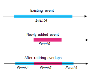
- Überlappungen stilllegen: Das System passt den Messwert sowie das Start- und Enddatum vorhandener Objekte so an, dass das neue Objekt keine Überlappung im Hinblick auf Zeit- und Messwerte verursacht.
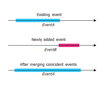
- Lagegleiche Objekte zusammenführen: Wenn alle Attributwerte für ein neues Objekt mit denen eines vorhandenen Objekts identisch sind und das neue Objekt im Hinblick auf die Messwerte an das vorhandene Objekt angrenzt oder dieses überlappt, wird das neue Objekt mit dem vorhandenen Objekt zusammengeführt und der Messwertbereich entsprechend erweitert.
- Nicht auf der Route liegende Messwerte vermeiden: Mit dieser Datenvalidierungsoption wird sichergestellt, dass die Eingabemesswerte für Von- und Bis-Messwerte innerhalb des Minimal- und Maximalbereichs der Messwerte auf der ausgewählten Route liegen.
- Objekte auf dominanten Routen speichern: In einem Abschnitt mit parallelen Routen werden Objekte auf der dominanten Route gespeichert. Wenn diese Option aktiviert ist, können Sie bei parallelen Abschnitten auf der ausgewählten Route auswählen, welcher Route Objekte auf dem jeweiligen parallelen Abschnitt hinzugefügt werden sollen. Diese Option ist verfügbar, wenn für das ausgewählte Netzwerk Dominanzregeln konfiguriert sind.
- Überlappungen stilllegen: Das System passt den Messwert sowie das Start- und Enddatum vorhandener Objekte so an, dass das neue Objekt keine Überlappung im Hinblick auf Zeit- und Messwerte verursacht.
- Check the Save events to dominant routes check box.
This dominant routes option can be configured to be checked or not checked by default using the Event Editor configuration file.
- Click Next.
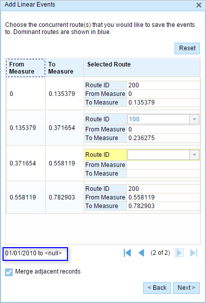
The route dominance table appears.
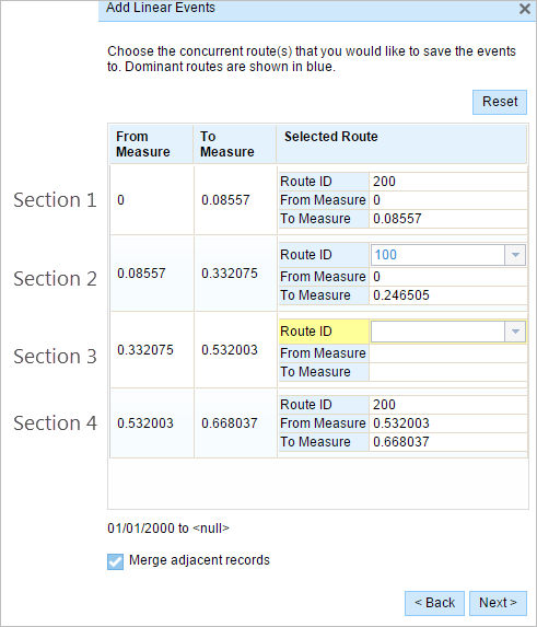
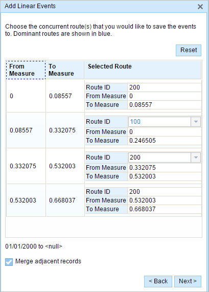
The From Measure and To Measure columns show the values for each section of the chosen route from the previous pane. The From Measure and To Measure boxes under Route ID show the value for each dominant route where the events will be added.
A black route ID without a drop-down arrow signifies that there was a single route in that section. A blue route ID with a drop-down arrow signifies that there are concurrent routes in that section, and the blue route is selected by the software based on the route dominance rules. You can select any other route using the drop-down arrow.
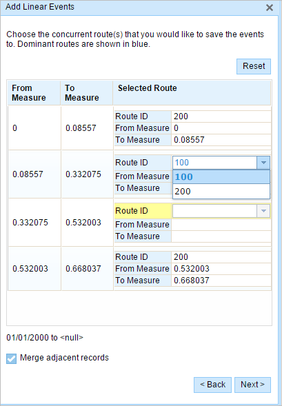
A yellow route ID box with a drop-down arrow signifies that there is an ambiguous situation in selecting the dominant route, as there is a tie in the route names of route 200 and route 300. In this case, you need to manually select a route ID using the drop-down arrow. The yellow color disappears once you've manually selected a route.
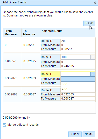
Select route 200. If you check the Merge adjacent records check box, the records in sections 3 and 4 will be merged since they have the same route ID.
- Click Next.
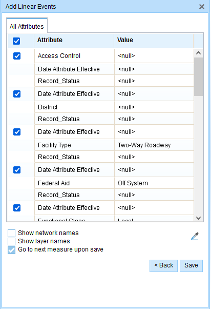
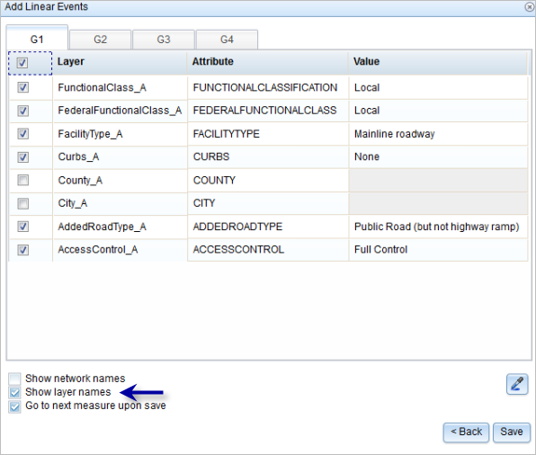
The tab showing the attribute set for the events opens. The event fields are shown under attribute group G1.
Hinweis:
You can check the check boxes to add data for specific events within the attribute set. No records are added for the events that are not checked. As shown in the following image, no records are added to the County_A and City_A events.
- Geben Sie die Attributinformationen für das neue Objekt in die durch Attribut-Sets definierten Tabellen ein.
Sie können das Werkzeug Attributwerte kopieren
 verwenden, um Objektattribute aus einer anderen Route zu kopieren. Klicken Sie auf das Werkzeug, und klicken Sie auf eine Route auf der Karte, um die Objektattribute zu kopieren.
Event Editor verwendet das auf der Registerkarte Bearbeiten angezeigte Standard-Attribut-Set. Sie können das Attribut-Set ändern, um benutzerdefinierte Attribut-Sets zu erstellen oder das vom Administrator konfigurierte Attribut-Set verwenden.
- Verwenden Sie die folgenden Optionen, um auf weitere Informationen im Attribut-Set zuzugreifen:
- Aktivieren Sie das Kontrollkästchen Netzwerkname anzeigen, um das LRS-Netzwerk anzuzeigen, das mit dem ausgewählten Objekt-Layer verknüpft ist.
- Die Attribute in den durch Attribut-Sets definierten Tabellen können aus mehr als einem Objekt-Layer stammen. Wenn Sie den Quellobjekt-Layer für die einzelnen Attribute identifizieren möchten, aktivieren Sie das Kontrollkästchen Layer-Namen anzeigen.
- Check the Go to the next measure upon save check box to prepopulate the From measure value using the To Measure value of the present section to continue the event creation process.
- Klicken Sie auf Speichern.
Die neuen linearen Objekte werden erstellt und auf der Karte angezeigt. Nachdem die neu hinzugefügten Linienobjekte gespeichert wurden, wird unten rechts eine Bestätigungsmeldung angezeigt.
Nachdem ein Objekt erfolgreich erstellt wurde, stehen Ihnen die beiden folgenden Optionen zur Verfügung, um die Route weiter zu charakterisieren:
- Klicken Sie auf Neue Bearbeitung, um alle Eingabeeinträge im Widget zu löschen und die Standardwerte aus der Geodatabase in der Attributtabelle wiederherzustellen.
- Klicken Sie auf Nächste Bearbeitung, um alle vorhandenen Einträge im Widget und in der Attributtabelle beizubehalten. Auf diese Weise lassen sich ähnliche Merkmale komfortabel und schnell bearbeiten.
Concurrent routes with different time ranges
The following image shows concurrent routes with different time ranges: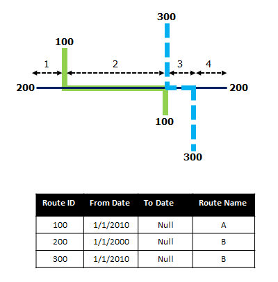
Route 200 has the From Date value of 1/1/2000, whereas route 100 and route 300 have the From Date value of 1/1/2010. Therefore, if the selected start date of the event is 1/1/2000, there are two route time ranges:
- 1/1/2000 to 1/1/2010, when only route 200 existed.
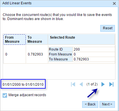
- 1/1/2010 to Null, when all three routes existed.
